

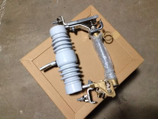
Fuse Cutout, Drop out Fuse 11-38kv
CUT-OUT Gama 20 kV a 36 kV- Circuito Principal 200 A- Ith 8 kA.- Montaje Vertical- Tubo Fusible de 100 A- Norma CEI 282-;
Basic Info
| Model NO. | Load Break 38KV 200A |
| Standard | IEC IEEE |
| 12 | Kv |
| 36 | Kv |
| 24 | Kv |
| 27 | Kv |
| 15 | Kv |
| 33 | Kv |
| 38 | Kv |
| Transport Package | Cartons Pallets Wooden Case |
| Specification | IEC282-2 IEEEc37-41 |
| Trademark | OEIpower |
| Origin | China Nanyang |
| HS Code | 85351000 |
| Production Capacity | 100000 |
Product Description
CUT-OUTGama 20 kV a 36 kV- Circuito Principal 200 A- Ith 8 kA.- Montaje Vertical- Tubo Fusible de 100 A- Norma CEI 282-2- Tubo Fusible compatible con losestándar norteamericanos.- Este modelo permite el montajede la Autoválvula directamentesobre la escuadra de fijación.- Eslabones fusible:de 2 Amp. a 100 Amp.- Porcelana de color gris, efectoAntivandálico.-- Montaje sencillo gracias a sustornillos de fijación anti-giro.- No es necesaria ningunaherramienta para cambiar eleslabónLa base cortacircuitos en "V" monta aisladores de columna conarmaduras metálicas externas y línea de fuga en función de los nivelesde contaminación I-III-IV asignados.Su diseño permite el accionamiento por pértiga desde una posición mascómoda para la maniobra, al conseguir un ángulo de 45º con respecto ala base de sujección.Incorpora un tubo fusible con capacidad para eslabones de hasta 100A, y es totalmente intercambiable con los modelos de una columna ymodelos de otros fabricantes.El interior del tubo portafusible está constituido por un recubrimientovegetal lo que le confiere un poder de extinción superior a otrosmodelos (según fabricante).El Seccionalizador en "V" monta aisladores de columna conarmaduras metálicas externas y línea de fuga en función de los nivelesde contaminación I-III-IV asignados.Su diseño permite el accionamiento por pértiga desde una posición mascómoda para la maniobra, al conseguir un ángulo de 45º con respecto ala base de sujección.
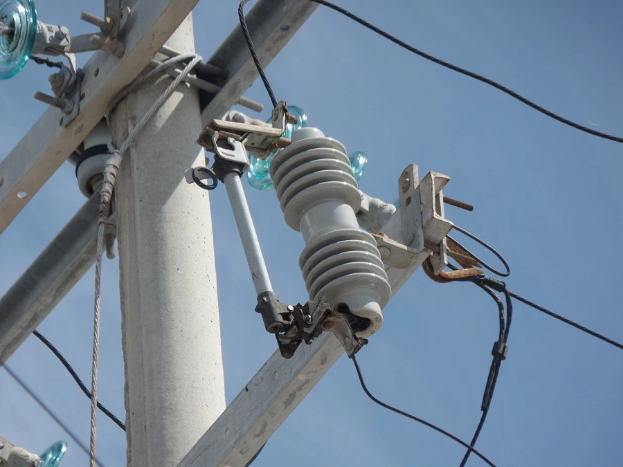
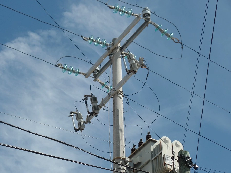
The Fuse Cutout type DHE was developed to operate in overhead distribution systems rated at 12-15 kV and 15-27,kV or 27-38 kV grounded systems with 100 or 200 A nominal currents.
Especially designed to protect transformers, capacitors, cables or lines.
It is robust construction, made of rigorously tested material, will interrupt all faults under the
most severe conditions, maintaining mechanical and electric characteristics.
The inserts, hardware and structural bolts and nuts are made from heavy galvanized steel.
The Fuse Cutout type OEI PRW can be applied on all three-phase system rated at or below the maximum operational rating of the cutout. In highly polluted environments or environments with high levels of salinity, a cutout may be used with a higher nominal rating than
that of the system where it is being installed, where the insulator will have a greater leakage distance to ground, allowing for
increased safety against discharge. For an even better protection against abrasions, the hardware may be supplied in stainless
steel. The fuse cutout type OEI PRW has attachment hooks in aluminum.
The Fuseholder has a stainless steel flipper, which associated with a spring doesn't allow the fuse link to be subject to traction
forces of over 3 Kgf, especially during closing. This me chanism also allows for high speed fuse link separation. The fuse cutout
type OEI PRW allows for the insertion of the fuse tube in a precise man ner and always in perfect alignment, due to the large distance
between the grunion pocket. Lower contact, silver-to-silver, provide du el current path, independent of hinge pivot. Stainless-steel
back-up springs prevent arcing when tube rises in hinge during recoil. The fuse cutout type OEI PRW may be transformed into a DICONNECT up to 300 A, by simply changing the fuse tube for an electrolytic copper blade.
The DHE Fuse Cutouts conform to ANSI and IEC standards, with independent tests performed At:
CPRI Always use quality fuse links. Only they can assure excellent performance.
DROP OUT FUSES11Kv
| N/O | DETAIL | DATA | ||
| 1 | Description | 11kV Fuse link assembly complete with fuse carrier rated at 100A and mounting bracket to PIESA 002. (See Figure 1 to Figure 12 below) | ||
| 2 | System conditions of service a) nominal Voltage (Un) r.m.s | kV | 11 | |
| b) maximum system voltage (Um) r.m.s | KV | 12 | ||
| c) earthing | Effective & non effective | |||
| d) Frequency | Hz | 50 | ||
| 3 | Site conditions of service a) altitude | m | 1400 | |
| b) Operating Ambient temperature | °C | -1 to 40 | ||
| c) Humidity | % | 85 | ||
| 4 | Rating | |||
| a) Nominal voltage | kV | 11 | ||
| b) Rated current | Fuse carrier | A | 100 | |
| Cut out base | A | 200 | ||
| 5 | Electrical components | |||
| a) Insulator material specification | Porcelain | |||
| Dielectric strength | ||||
| Lightning impulse withstand (1.2/50) | kV | 95 | ||
| Power frequency wet withstand voltage r.m.s | kV | 28 | ||
| 6 | Specific creepage distance | mm/kV | 25 | |
| 7 | General information to be provided with bid: | |||
| Drawings and brochures showing outline and general arrangement | Yes/No | Yes | |
| b) Detailed drawings of all items showing critical tolerances to be provided with bid | Yes/No | Yes | |
| 8 | Previous Type test report/certificate on complete fuse link assembly to be provided with bid | Yes/No | Yes |
| 10 | Routine tests (acceptance tests on sample Product) to be provided on delivery | Yes/No | Yes |
| 11 | Applicable standard | PIESA 002 | |
| 12 | Other applicable standards | NRS 035 SABS IEC 60282-2 SABS IEC 60186 BS 137 part 2 |
3. FURTHER REQUIREMENTS:
3.1 There shall be no rivets in the parts that form the current path
3.2 Water shall not be able to accumulate on any part of the equipment nor shall any feature introduce moisture into any component.
3.3 The design shall incorporate all reasonable precautions and provisions for the safety of personnel concerned with the operation and maintenance of the same.
3.4 The current path shall be such that load current shall only flow through high conductive materials such as copper and its alloys. Load current shall not be permitted to flow through ferrous components, springs, or spring-loaded mechanisms.
3.5 All load current paths shall be so designed that the relevant parts of the solid link assembly are capable of carrying the specified rated current without exceeding the permitted temperature rise in SABS IEC 60282-2
3.6 Contacts shall be based on the line contact principle and there shall be no welds on the contact parts. The construction of the Drop out fuse base and the solid link shall ensure their mutual alignment during closure.
3.7 The solid link should have an eye and an operating tongue.
4. MARKING AND IDENTIFICATION
4.1 Markings to conform to SABS IEC 60282-2
4.2 In addition , the following markings must be included : ZESCO Indent No.
3.0 SUPPLIMENTARY NOTES
3.3 Suppliers should give sufficient information including drawings (which must be brief, clear and to the point) on how their drop out fuse designs addresses these requirements. Further, Suppliers may offer better alternatives that are of cost benefits to. It is therefore imperative that schedule "B" is completed by the tenderer. Any deviations/modifications/alternatives specification must be listed in schedule "C." No deviations/modifications/alternatives will be recognised unless they are listed in schedule "C"
3.4 The drawings to be submitted by the tenderer must include the following:
3.4.1 Critical tolerances
3.4.2 Show details of the insulator, the fuse carrier, the solid-link, the upper contact, the lower contact, the cutout base and the bracket for fixing to either wooden or steel cross arm.
3.5 The type tests to be submitted must be those issued by internationally recognised testing authority.
3.6 All salient design details of each item required shall be supplied with the tender.
33kV
| N/ O | DETAIL | DATA | ||
| 1 | Description | 33 kV Fuse link assembly complete with fuse carrier rated at 100A and mounting bracket to PIESA 002. (See Figure 1 to Figure 12 below) | ||
| 2 | System conditions of service a) nominal Voltage (Un) r.m.s | kV | 33 | |
| b) maximum system voltage (Um) r.m.s | KV | 36 | ||
| c) earthing | Effective & non effective | |||
| d) Frequency | Hz | 50 | ||
| 3 | Site conditions of service a) altitude | m | 1400 | |
| b) Operating Ambient temperature | °C | -1 to 40 | ||
| c) Humidity | % | 85 | ||
| 4 | Rating | |||
| a) Nominal voltage | kV | 33 | ||
| b) Rated current | Fuse carrier | A | 100 | |
| Cut out base | A | 200 | ||
| 5 | Electrical components | |||
| a) Insulator material specification | Porcelain | |||
| Dielectric strength | ||||
| Lightning impulse withstand (1.2/50) | kV | 170 | ||
| Power frequency wet withstand voltage r.m.s | kV | 70 | ||
| 6 | Specific creepage distance | mm/kV | 25 | |
| 7 | General information to be provided with bid: Drawings and brochures showing outline and general arrangement | Yes/No | Yes |
| b) Detailed drawings of all items showing critical tolerances to be provided with bid | Yes/No | Yes | |
| 8 | Previous Type test report/certificate on complete fuse link assembly to be provided with bid | Yes/No | Yes |
| 10 | Routine tests (acceptance tests on sample Product) to be provided on delivery | Yes/No | Yes |
| 11 | Applicable standard | PIESA 002 | |
| 12 | Other applicable standards | NRS 035 SABS IEC 60282-2 SABS IEC 60186 BS 137 part 2 |
5. FURTHER REQUIREMENTS:
5.1 There shall be no rivets in the parts that form the current path
5.2 Water shall not be able to accumulate on any part of the equipment nor shall any feature introduce moisture into any component.
5.3 The design shall incorporate all reasonable precautions and provisions for the safety of personnel concerned with the operation and maintenance of the
same.
5.4 The current path shall be such that load current shall only flow through high conductive materials such as copper and its alloys. Load current shall not be permitted to flow through ferrous components, springs, or spring-loaded mechanisms.
5.5 All load current paths shall be so designed that the relevant parts of the solid link assembly are capable of carrying the specified rated current without exceeding the permitted temperature rise in SABS IEC 60282-2
5.6 Contacts shall be based on the line contact principle and there shall be no welds on the contact parts. The construction of the Drop out fuse base and the solid link shall ensure their mutual alignment during closure.
5.7 The solid link should have an eye and an operating tongue.
6. MARKING AND IDENTIFICATION
6.1 Markings to conform to SABS IEC 60282-2
3.0 SUPPLIMENTARY NOTES
3.5 Suppliers should give sufficient information including drawings (which must
be brief, clear and to the point) on how their drop out fuse designs addresses these requirements. Further, Suppliers may offer better alternatives that are of cost benefits
3.6 The drawings to be submitted by the tenderer must include the following:
3.6.1 Critical tolerances
3.6.2 Show details of the insulator, the fuse carrier, the solid-link, the
upper contact, the lower contact, the cutout base and the bracket for fixing to either wooden or steel cross arm.
3.7 The type tests to be submitted must be those issued by internationally recognised testing authority.
You may also like


Send inquiry
Send now